Introduction
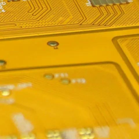
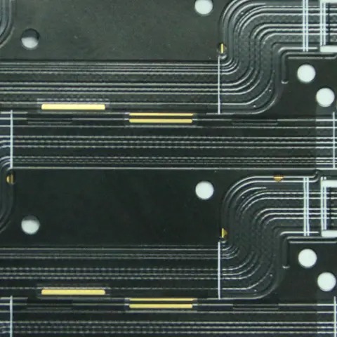
Double-sided Flexible Printed Circuits (FPC) are a critical advancement in modern electronics manufacturing, combining flexibility with the functionality of complex circuit layouts. Unlike single-sided boards, where the conductive pattern exists on only one surface, double-sided FPCs feature conductive traces on both the top and bottom layers of the flexible substrate. These two conductive layers are interconnected using plated through-holes, enabling more intricate circuit designs without increasing the overall size of the board. This feature is essential for compact electronic devices such as automotive control modules, steering wheel switch panels, wearable technology, and medical equipment.
The primary advantage of double-sided FPC lies in its ability to maximize circuit density while retaining the physical flexibility needed for applications where rigid boards would fail. By using a polyimide or polyester substrate, manufacturers ensure the board remains thin, lightweight, and able to bend or fold to fit into compact product housings. This makes them particularly suitable for environments where vibration, limited space, and mechanical stress are present.
Additionally, the design of double-sided FPCs supports more complex signal routing and better electrical performance. Components can be mounted on either side, and signals can traverse between layers through vias, minimizing crosstalk and improving signal integrity. This balance between mechanical adaptability and high-density electrical functionality makes double-sided FPCs an indispensable choice in modern electronics engineering.
In the following sections, we will explore in detail how double-sided PCBs work, their manufacturing process, performance benefits, common applications, and key considerations when selecting them for a project. We will also provide a detailed FAQ section and a comparative table to clarify their distinctions from other PCB types.

Structure and Working Principles of Double-sided FPC
The core structure of a double-sided FPC includes two copper layers separated by a dielectric substrate, typically made from flexible polyimide. Each copper layer contains intricate conductive pathways that carry electrical signals between various components. These layers are interconnected using plated through-holes (PTH)—small drilled holes lined with conductive material that enable current to flow from one side to the other.
When a device operates, signals travel along the copper traces from one component to another. If the route requires crossing over another signal path, the trace can be moved to the opposite side of the board through a via, thereby eliminating signal interference. This capability is what allows double-sided FPCs to support more complex and compact circuit layouts than single-sided boards.
The working mechanism can be summarized as follows:
Signal Routing Across Layers – Electrical signals move between the two copper layers via plated through-holes, enabling compact and intricate designs.
Component Mounting Flexibility – Components such as resistors, capacitors, and integrated circuits can be placed on both sides, optimizing space usage.
Mechanical Flexibility – The polyimide base allows the board to bend without damaging the copper traces, making it ideal for folding into tight spaces.
Thermal Management – The dual-layer design can better distribute heat generated by high-performance components, improving reliability.
The combination of these factors enables double-sided FPCs to handle higher circuit complexity while maintaining their physical adaptability. This is why they are frequently used in automotive steering wheel control circuits, where multiple signal paths must be accommodated in a compact, curved space without sacrificing durability.
Manufacturing Process of Double-sided FPC
Manufacturing a double-sided flexible PCB involves multiple precision-controlled steps to ensure electrical performance and mechanical reliability. The process typically follows these stages:
Base Material Preparation – A flexible substrate, usually polyimide, is laminated with copper foil on both sides. The copper thickness is selected based on the application’s current-carrying requirements.
Photoresist Application and Imaging – Both sides are coated with a light-sensitive photoresist layer. Circuit patterns are transferred to the copper surface using UV light through a photomask.
Etching – Unwanted copper is removed using chemical etching, leaving behind the desired circuit patterns on both sides.
Drilling and Plating – Precision drilling machines create vias that are then plated with copper to connect the top and bottom circuit layers electrically.
Solder Mask and Surface Finish – A solder mask is applied to protect the copper traces from oxidation and prevent solder bridging during component assembly. Finishes like ENIG (Electroless Nickel Immersion Gold) or OSP (Organic Solderability Preservatives) ensure solderability and corrosion resistance.
Testing and Quality Control – Each FPC undergoes electrical continuity tests and mechanical bending tests to verify performance before shipment.
This meticulous process ensures that the final product offers high conductivity, mechanical flexibility, and durability under repeated bending cycles. The precise alignment of the two copper layers during manufacturing is crucial—any misalignment could cause signal integrity issues or mechanical failure during operation.
Advantages of Double-sided FPC
Double-sided FPCs provide several distinct benefits over both single-sided flexible boards and rigid PCBs:
Higher Circuit Density – Two copper layers allow more routing options, enabling complex designs in smaller footprints.
Compact Product Design – Their thin and bendable nature helps fit electronics into unconventional or curved shapes.
Improved Electrical Performance – Reduced need for long signal paths lowers resistance and minimizes signal loss.
Cost Efficiency for Complex Designs – Compared to multilayer boards, double-sided FPCs offer a balance between complexity and cost.
Enhanced Reliability in Dynamic Applications – The flexible substrate absorbs vibrations, reducing the risk of solder joint failure.
These advantages explain why double-sided FPCs are commonly found in modern automotive electronics, aerospace instruments, portable consumer electronics, and wearable medical devices. Their ability to combine electrical sophistication with mechanical adaptability gives engineers greater design freedom without compromising performance.

Common Applications and Use Cases
Double-sided FPCs are versatile and widely applied across industries:
Automotive Systems – Used in steering wheel switches, dashboard displays, and infotainment systems, where flexibility and compactness are vital.
Medical Devices – Applied in diagnostic tools, wearable health monitors, and surgical instruments due to their lightweight and bendable properties.
Consumer Electronics – Found in foldable smartphones, tablets, and cameras to enable thin, space-saving designs.
Industrial Equipment – Utilized in robotics, control panels, and sensor assemblies requiring high durability under mechanical stress.
The table below summarizes the key differences between single-sided, double-sided, and rigid PCBs:
| Feature | Single-sided FPC | Double-sided FPC | Rigid PCB |
| Copper Layers | 1 | 2 | 2+ |
| Flexibility | High | High | Low |
| Circuit Density | Low | Medium-High | High |
| Cost | Low | Moderate | Varies |
| Applications | Simple circuits | Complex flexible | Rigid, high-power |
FAQs About Double-sided FPC
Q1: What is the main difference between a double-sided FPC and a single-sided FPC?
A double-sided FPC has copper traces on both sides of the flexible substrate, connected through vias, allowing more complex and compact circuit designs compared to a single-sided board.
Q2: Can double-sided FPCs handle high-current applications?
Yes, but the copper thickness and trace width must be designed appropriately. For very high-current applications, multilayer designs or reinforced copper may be required.
Q3: Are double-sided FPCs more expensive than single-sided ones?
Generally, yes. The additional copper layer, drilling, and plating processes increase production costs, but they are still more cost-effective than full multilayer boards for moderately complex designs.
Q4: How durable are double-sided FPCs?
When manufactured with quality materials and proper design rules, they can endure thousands of bending cycles without significant degradation in performance.
Q5: What design software is best for creating double-sided FPC layouts?
Most professional PCB design software such as Altium Designer, KiCad, and OrCAD can handle double-sided flexible PCB layouts.


